Causes Of Cracks In The Impeller Of Corrosion-Resistant Pump
TIME:2024-06-04 Author:admin Views:
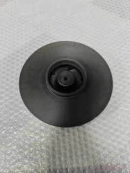
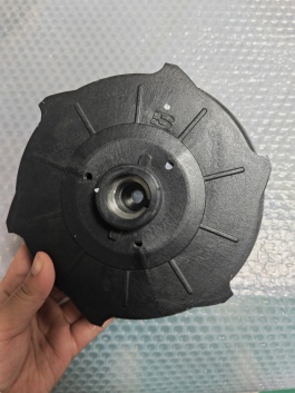
● Structural analysis of the turbine
The corrosion-resistant chemical pump impeller is composed of front cover plate, rear cover plate, vane, hub and other components. The design of the acute angle of the interface between the blades and the front cover plate is narrow, which is easy to cause stress concentration. Under the acting mutual load, the blades are stretched and overload stresses are formed at the joint between the blades and the former cover plate, leading to reverse contraction and crack formation at the joint.
Fracture pattern analysis: a blade sample was cut from the impeller and cracks were observed to extend from the tip of the blade towards the rear cover plate and the joint between the blade and the hub. In fact, the total length of the crack is 70 ~ 80 mm. Fatigue steps perpendicular to the direction of crack extension can be observed from the blade cross-section, which is the basic macroscopic feature of metal fatigue fracture. The fracture was viewed with a scanning electron microscope and the beach diagram formed by the fatigue stage was clearly visible. Fatigue streaks in low sliding coefficient steels are getting shorter and shorter, and it is difficult to observe typical fatigue streaks at higher and higher impeller speeds. However the fracture surface of the blade is straight and a beach pattern formed by fatigue arcs is present on the fracture surface.
● Improvement of impeller structure
1. Blade and back thickness cover plate
The design thickness of the old impeller blade of chemical pump is 5mm, the design thickness of the new impeller blade is 7mm, the design thickness of the old impeller back cover plate is 5mm, the design thickness of the new impeller back cover plate is 8.6mm.
2.The total length of the leading edge of the vane of corrosion-resistant center-opening pump
3. In order to solve the above problems, the new two-stage impeller shortens the leading edge of the blades to the inner diameter of the impeller and increases the root position to the front and back cover plates, which makes machining difficult and the thickness and size control accuracy high. The total length of the blade leading edge is shortened, sharp corners are eliminated, and stress concentration problems are greatly reduced.
4. Finite element analysis of blade stresses
5. Due to the short design scheme, the peak stresses at the inlet corners of the old impeller blades exceeded the tensile strength of the blade material during normal operation, low-flow operation and overspeed operation. However, after optimizing the design scheme, the local peak stress of the new impeller blade is significantly reduced to 254 MPa, which is much lower than the value of the yield strength design scheme, solving the problem of insufficient tensile strength at the tip corner of the blade, and meeting the requirements of the design scheme.

